Requirements

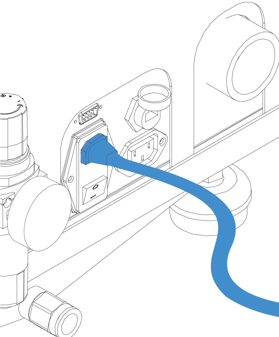
● 220 volts ± %5, 50Hz, 1 Kw, Single phase main electric output.

● Minimum 3 x 1.5mm Power cable line and 16 Amp fuse installation.

● Grounding type Class 3 ( Class 3 Grounding requirements are max 100 Ω grounding resistance and 500 V megger measuring instrument).

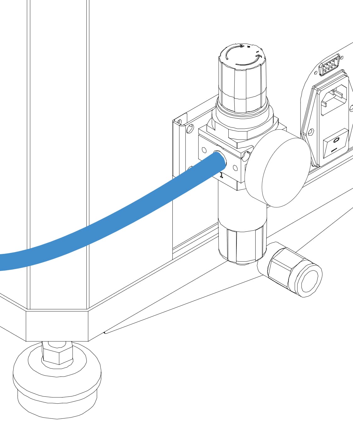
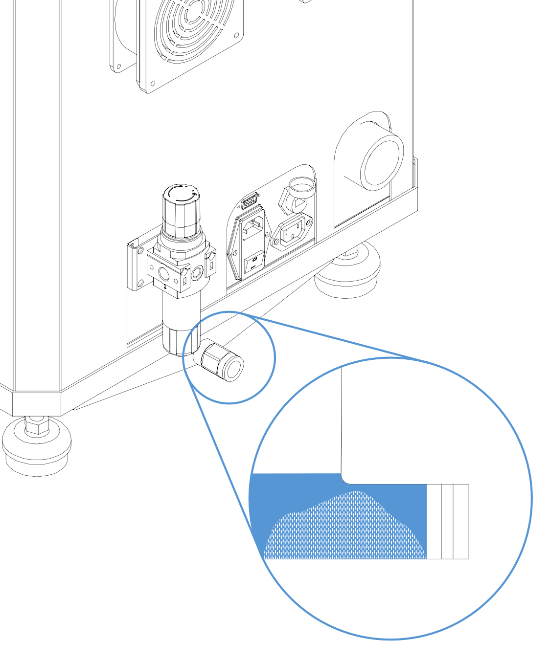
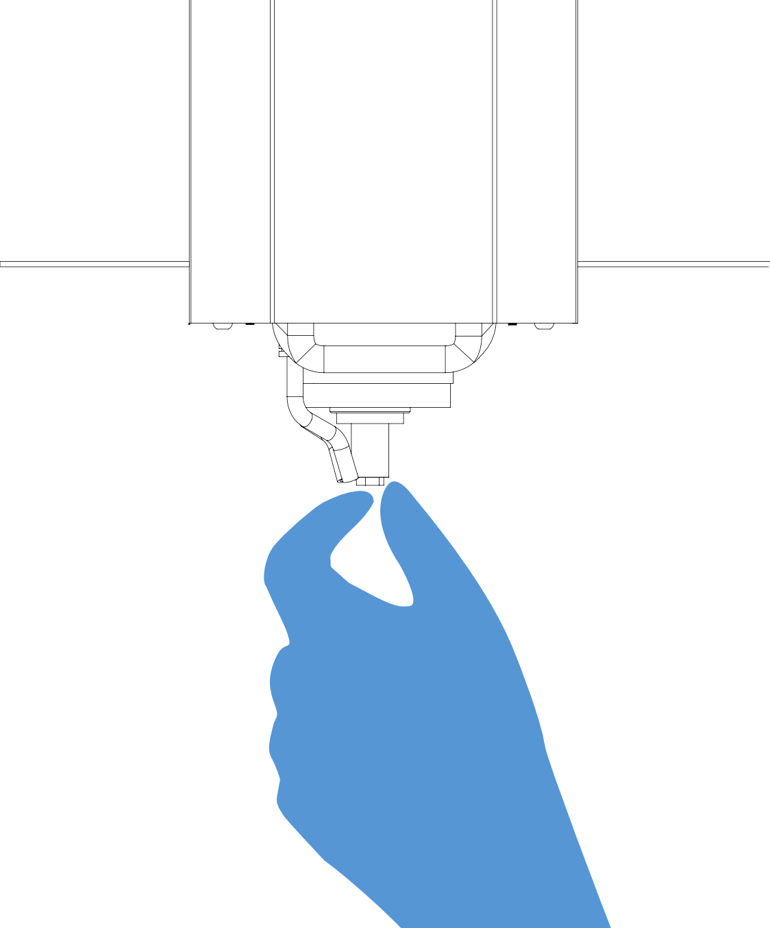
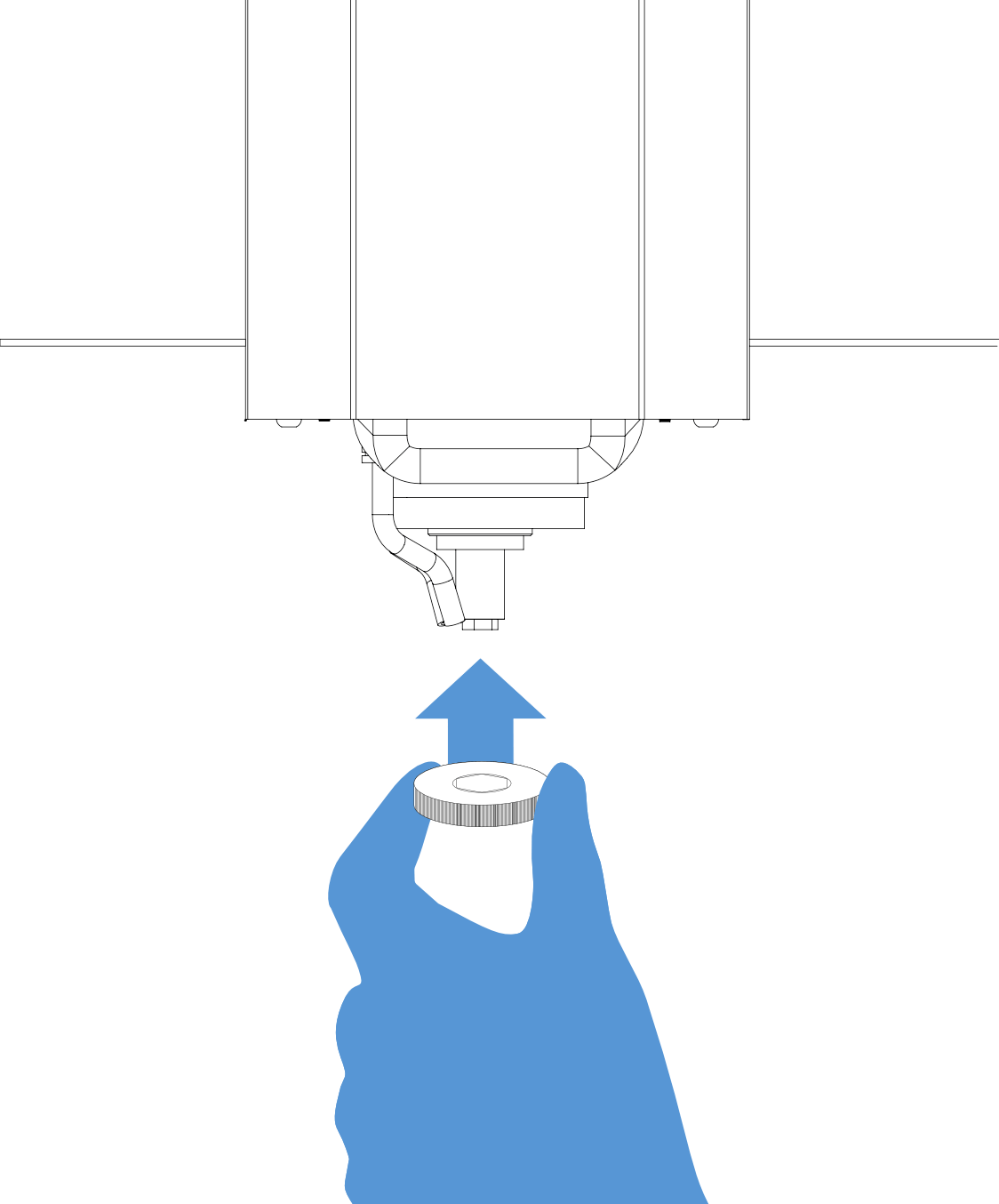
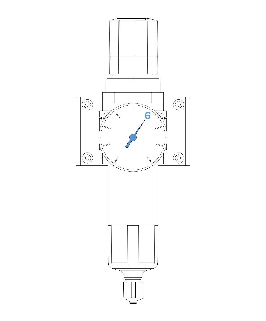
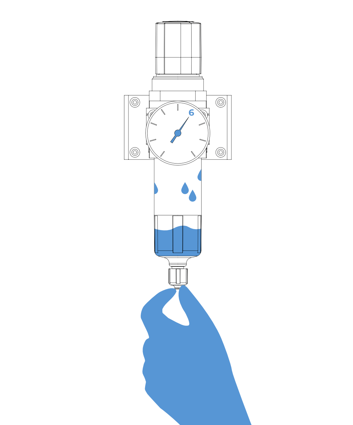
● Minimum P=4,5 bar compressed air (ISO 9001, ISO 14001 & ISO 1217).

● Minimum 60 L/min flow rate. Recommended 150 L/min flow rate

● The Air line from the compressor to the Machine must be at least 3/4” in size.

● Manual valve for on/off.

● Solid impurities – Class 3 – Filter grade at least 5μm for solids

● Water content – Class 4 – max. Pressure dew point +3C

● Total oil content – Class 2 – max. Oil content 0.1mg/m3.

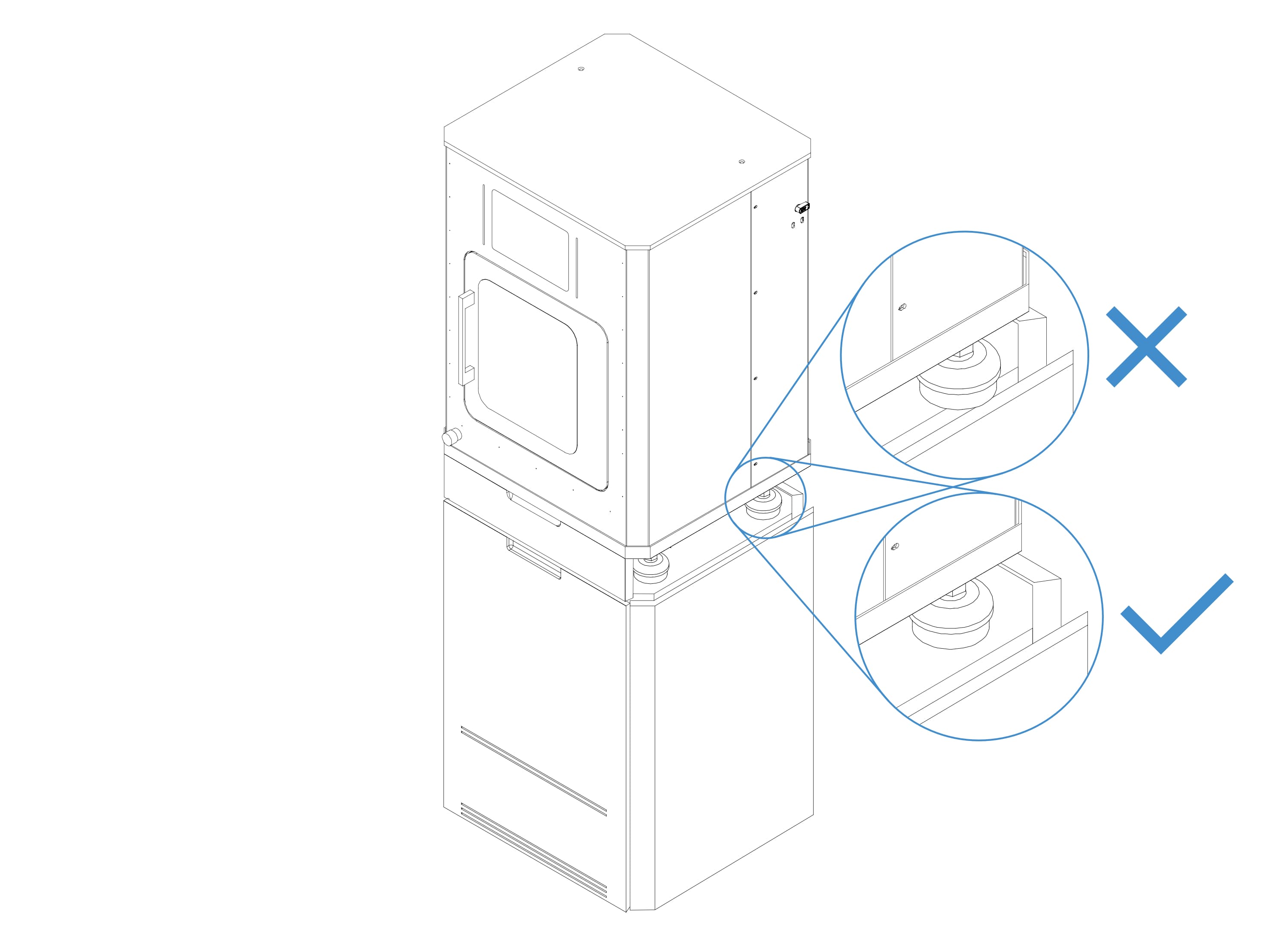
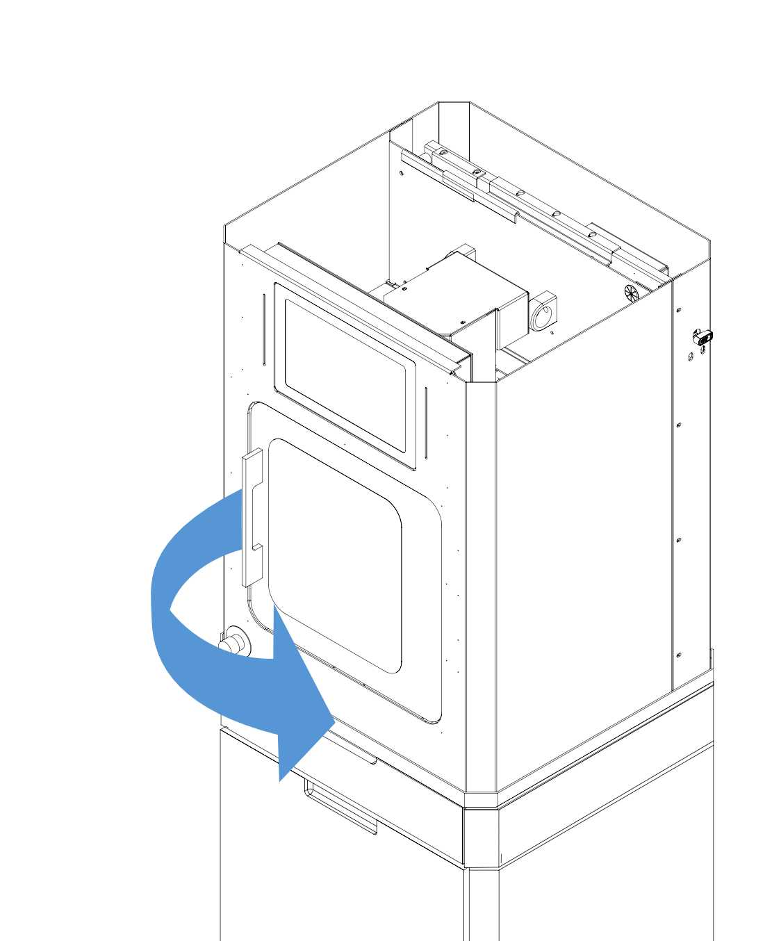
● The machine generates vibration while working therefore a smooth concrete floor surface should be prepared. Only a 5mm level difference is allowed throughout the machine base. The machine's surrounding should be clear.

● Between the wall and the machine, there should be a minimum distance of 50 cm.

● If the humidity and temperature of the compressed air are variable, then the drying system and air coolers should be installed.

● Compressed air temperature should be the same as the room temperature.

● The ambient temperature for machining conditions should be 20-25 °C degrees.

Cutting fluids can be found in our store.

To protect the machine from electricity blackouts, minimum 3,5 kVA Online UPS should be installed.

Atlas Copco GX2 Model air compressor is recommended.

Package information

D10

Description: Yenadent D10 CNC Machining Center

Width dimension: 65 cm

Depth dimension: 65 cm

Height dimension: 99 cm

Gross weight: 110 kg

Net weight: 90 kg

Options

Table

Width dimension: 65 cm

Depth dimension: 65 cm

Height dimension: 99 cm

Gross weight: 58 kg

Net weight: 38 kg

Liquid tank

Width dimension: 47 cm

Depth dimension: 57 cm

Height dimension: 58 cm

Gross weight: 21 kg

Net weight: 13 kg

Vacuum unit

Width dimension: 37 cm

Depth dimension: 47 cm

Height dimension: 59 cm

Gross weight: 19 kg

Net weight: 14 kg

Unboxing

Check the box warning labels for damages and if you see any warning or damage, please contact the courier company. Please check if the machine has been damaged after cutting the fixing straps. In case of immediate objections and feedback to your dealer or Yena Makina A.Ş, it will be possible to get results in problem-solving.

Placement

D10 table is an optional product.

Assembly

Air hose

Outer diameter: 12mm
Inner diameter: 8mm

Power cable

These are the optional products.

Warm-up

Warm-up is a necessary process for your machine to mill as intended.
Ideally, when you start your machine, the machine prompts you to warm up. 

If the machine is idle for about 2-3 hours, you need to do the warm-up again manually before starting milling.

After opening the warm-up file, click start to run the warm-up.

Placing the disc

Screw tightness should be just enough to hold the blocks so your block won't rotate while milling. If you overtighten you might damage your soft material blocks.

Place the desired block you will mill into the block holder.

Tighten the screws with provided allen key until the block is secured and won't move. 

Tool replacement

When changing a new tool or when you remove tool from the spindle, the tool length must be measured.

You can do the tool replacement either for changing, broken/worn-out tools or first time installing the tools. 

Press the "Replace tool" button on the Jog Control page of the program.
The tool table will come up on the opened page.

The Last tool is measuring spindle length.

● Click the number on the “No" column to select the tool number you want to identify or change.

● Select the type of tool you want to define or change from the "Type" section on the upper right.

● Click the “Replace Tool" button. 

On the screen, you will receive a message box that is prompting you, it will place the tool inside the spindle to its dedicated location.

You will receive a second message box that is asking if you could change the tool in this spindle position, or do you want to send the spindle to the home position for easier tool replacement.

When the "Replace Tool" operation is completed, you will see that the tool number information on the lower left side also changes.

Before clicking the collet button, make sure to hold the tool with your hands, to prevent the tool from falling. (This only applies to tool change)

When you receive the third message, you can now replace the tools by clicking the collet button. If this is your first-time tool installation, the spindle will be empty and again clicking the collet button you can place your tool inside the spindle.

In the new message that appears on the screen, click on the "OK" button, asking if you want to measure the length of the new tool.

Finally, after measuring the tool length, a message will appear on the screen informing you that the tool change process is finished. Click the "OK" button. Finish the tool change and installation process. 

Start milling

Click file at the top left side of the window and open batch jobs.

Double-click on the shown box, then select the file you want to process.


“Warm-up” is an example.

The “work in” section should always be “left

If you have one file, you. can click on “check file

If you have multiple files you can click on “check all

You can start to mill after clicking on “ start the job”


Stop milling

Press the "stop" button to stop axes movements.

Press the "CW" button to stop the spindle.

Press the "home" button to send axes to the home position.

Resume milling after interruption

The program will be called after you pressed the "yes" button.

Press the "start" button.

The program will resume where it left off when you press the "OK" button.

General cleaning

Do not blow compressed air into the machine.

Daily cleaning

 Make sure to clean your machine daily, so the dust and particles won't clog and prevent the axis movement.

You need to clean the inside of the machine thoroughly.

Collet cleaning

The spindle is both the most powerful and the most sensitive part of your machine. Even a slight vibration can cause imperfections.
Make sure to clean the spindle collet once a month with the collet cleaning kit you receive with the machine.

Open your collet and hold the tool with your hand if there is a tool inside the spindle. Remove the tool and leave the collet open.

Use the collet apparatus to loosen the collet. Then remove the collet by rotating it.

Put a little solution on to small brush and clean the insides of the collet.

Use conical cleaning part to clean inside the spindle. 

Screw your collet inside the spindle by rotating completely inside the spindle. Use the collet apparatus to gently tighten the collet. Make sure your collet is semi-tightly screwed into its place.

Drains cleaning

For better cutting liquid circulation, drains inside the machines should be checked and cleaned once a month.

Zirconia dust can collect inside the fitting and may prevent drainage.

The fitting can be cleaned by clearing the blockage with a stick-like object.

Tool measurement sensor probe cleaning

The dust and particles beneath the measurement probe can pile up and prevent the movement of the probe. This may produce miscalculations, can cause tool breaking, or even worse machine malfunction. 

The probe must be checked weekly. 

You can clean underneath of the probe with a brush. After cleaning check with if the probe is free to move.

Brush might not be enough with wet milling. Zirconia and cutting liquid can be hardened. If that is the case please use a penetrant/lubricant sprey such as Wd40.

Deep cleaning

Make sure to turn the machine and air off before starting.

Deep cleaning requires you to remove the machine cover to clean hard-to-reach areas of your machine easily.

After you have removed the front cover clean your machine throughly with an electric vacuum cleaner. Zirconia dust may cause malfunction for regular vacuums, we suggest an industrial vacuum.

Remove the top lid by removing its screws.

Open the door and you can reach all the places in the machine.

General maintenance

The need for maintenance is based on actual or imminent failure. Ideally, maintenance is carried out to keep equipment and systems running efficiently during at least their usual life cycle.

Make sure to have your machine in tip-top shape to keep the precision high.

Collet tightness checking

You should check your collet tightness once a month.

Also when the margins are thinner than expected, collet tightness is the first to examine. 

Checking air pressure and humidity

You can check both the air pressure from the gauge and humidity on the plastic tube on the conditioner which is located at the back.

You can check the air pressure from the gauge

You can check the humidity from the tube: You can tell from condensed water drops or water that has accumulated inside.

Calibration and measurement

Calibration is the act of comparing a device under test of an unknown value with a reference standard of a known value. A person typically performs a calibration to determine the error or verify the accuracy of the device under the test’s unknown value.

If your machine hasn't been running for more than 15 minutes before starting the calibration, be sure to run the machine warm-up program before starting the calibration.

Make sure that the calibration tool is present on your machine. If you do not have a calibration tool in the spindle or in your pick-up station, first install the calibration tool on your machine.

Connect the calibration disc sent with the machine to the disc holder of your machine. (10 to 14 mm wax discs)

Standard calibration

Press the "Calibration" button on the "Jog Control" page of the program.

Make sure the dotted place on the block is not milled. The part will be milled here.

Click the "Standard" button in the message box that appears on the screen.

Click the "Yes" button in the new message box on the screen. Your machine will automatically start processing the part for "Standard calibration" control.

When the standard calibration part finishes machining, your machine will automatically go to the home position and the message box will pop up where the measured values are entered in the part displayed on the screen.

Take the processed part out of the disc and measure the specified locations and write the values of the measured values in the specified boxes. Then click the "OK" button. After this operation, the Y and Z axes of your machine are calibrated.

B axis calibration

Press the "Calibration" button on the "Jog Control" page of the program.

Make sure the dotted place on the block is not milled. The part will be milled here.

Click the “B axis" button in the message box that appears on the screen.


Click the "Yes" button in the new message box on the screen. Your machine will automatically start processing the part for the “B axis” control.

When the B axis calibration part finishes machining, your machine will automatically go to the home position and the message box will pop up where the measured values are entered in the part displayed on the screen. 

Take the processed part out of the disc, measure the Z thickness of the specified locations, and write the values inside the corresponding boxes. Then click the "OK" button. After this operation, the X-axis of your machine is calibrated.

Product added to wishlist
Product added to compare.