Monthly back up for your MCTL folder could be beneficial in case of computer hardware/software failure or malfunction.
Navigate to this folder in your CNC computer.
This PC > Local Disc (C:)
Copy the "MCTL" folder to a safe storage device or a cloud service.
Initialization 51 problem
Check if you turn on the power button of your machine.
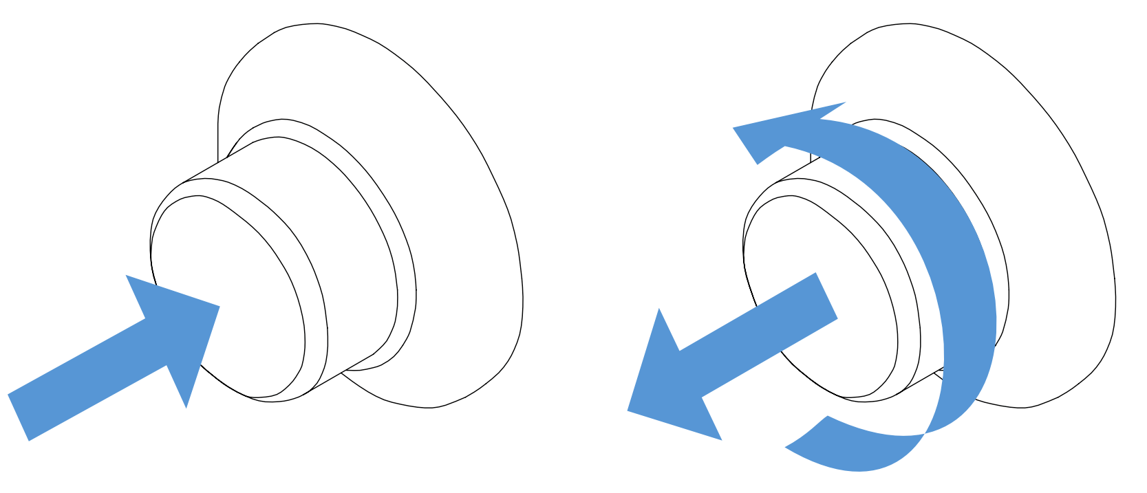
Check if your emergency button is pressed. If pressed, release it by rotating it.
Check if your USB cable that is connected to your tablet pc is loose or disconnected. Rarely USB ports might malfunctioning therefore you can check by changing the USB port as well.
Motor power is off problem
Check if the emergency button is pressed.
Axes move intermittently
Turn the CNC program off.
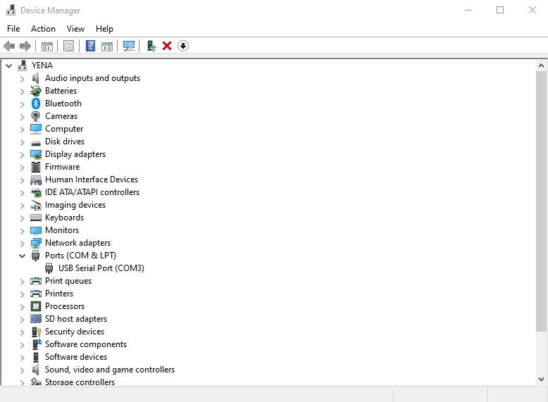
Check the windows COM latency timer.
Right-click on the USB serial port(COMX). Click on properties.
There might be more than one USB serial port. The Port can be identified by removing the USB cable. The USB serial port that is removed from the list
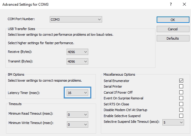
Select the "port settings" tab. Click on "Advanced..."
Adjust the latency timer to " 1 ". Click OK.
Restart computer.
Required parameters missing
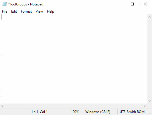
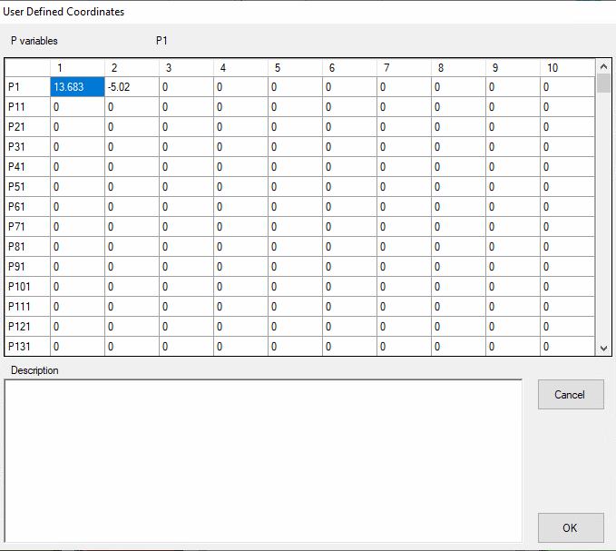
Check if the contents of the ToolGroups file is deleted.
Turn the CNC program off.
Navigate to this folder in your CNC computer.
This PC > Local Disc (C:) > MCTL > PARMS
Open the "ToolGroups.setup" file.
If the contents are empty, download, copy and replace the ToolGroup file.
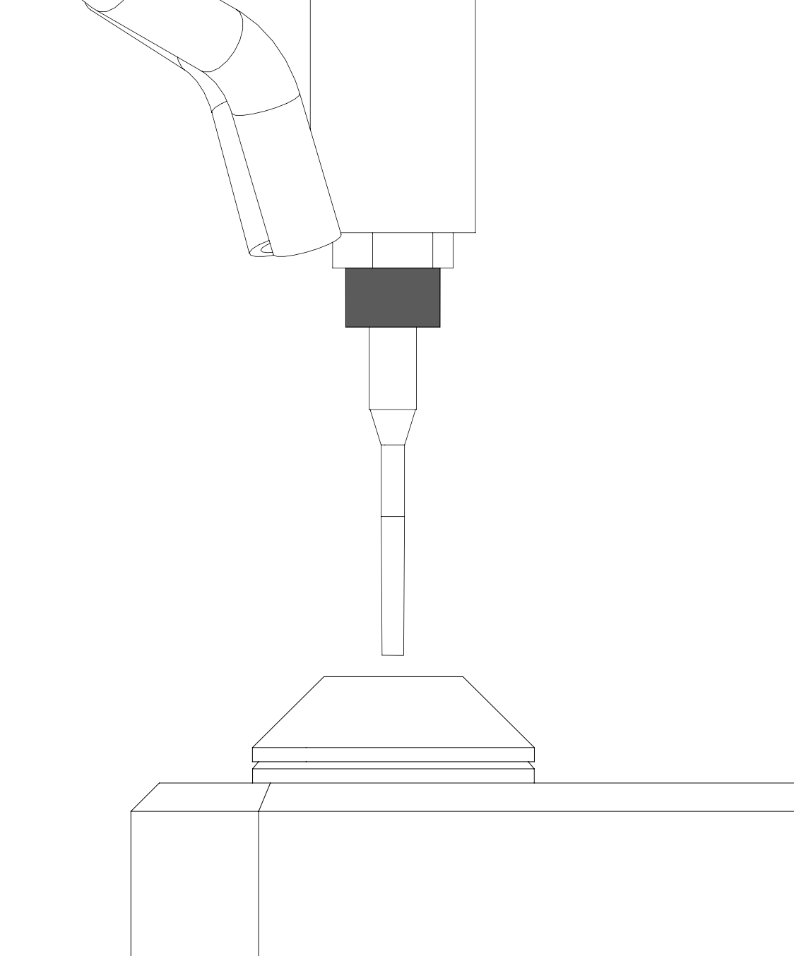
Lower the "feed rate" down to %20. Axes can crash since the control is on your hand.
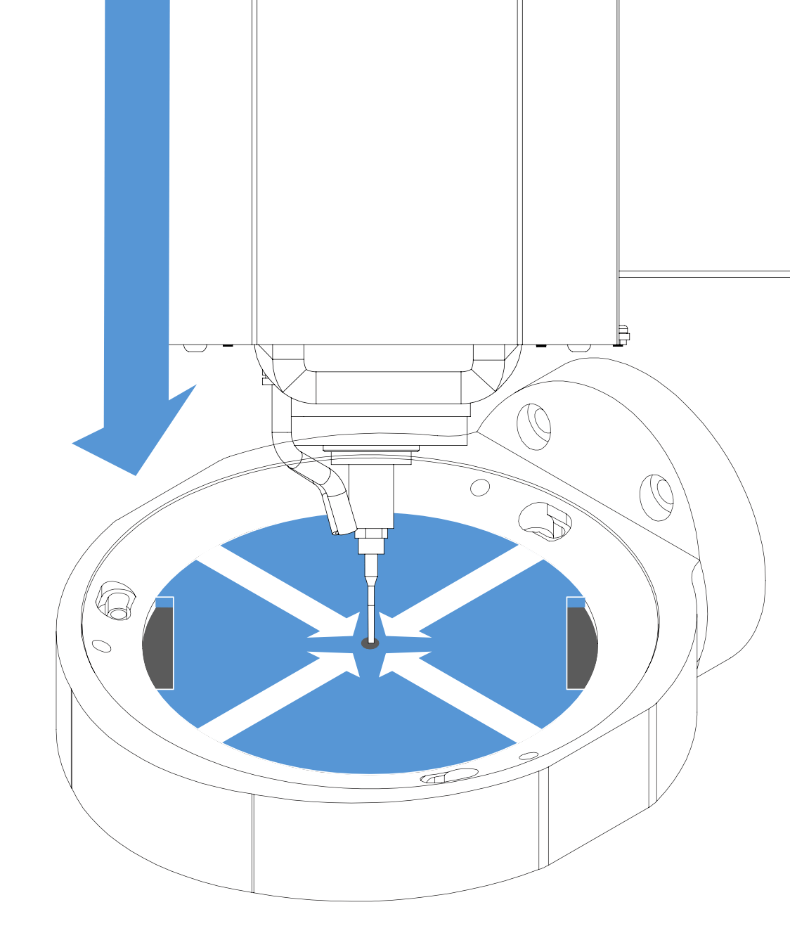
The tool does not need to completely go through the hole. If the template is used, the tool must not touch the template.
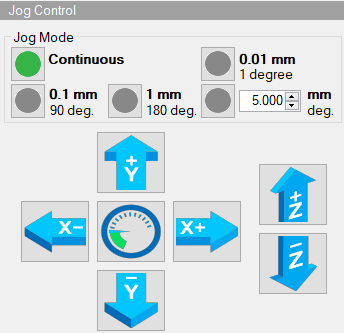
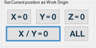
Center the tool by using the jog control buttons. Use 0.1mm when the tool is close to the center for more precision.
When the tool is a the center click on the "X/Y=0" button.
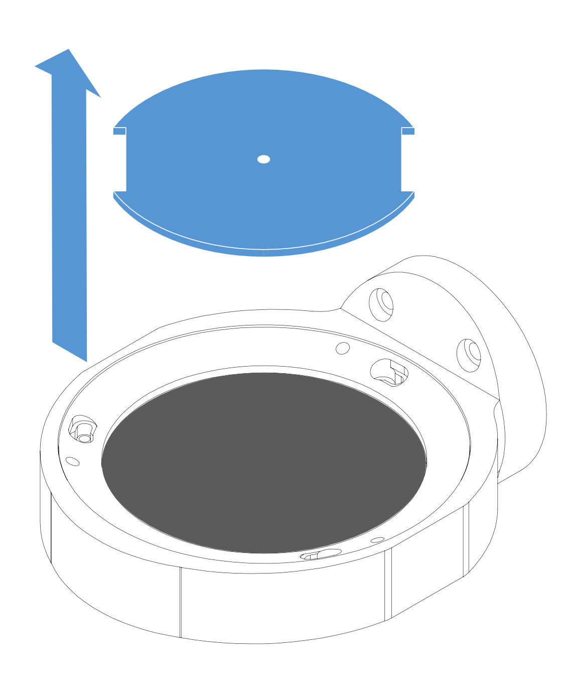
Move the Z-axis up, then remove the work origin disc.
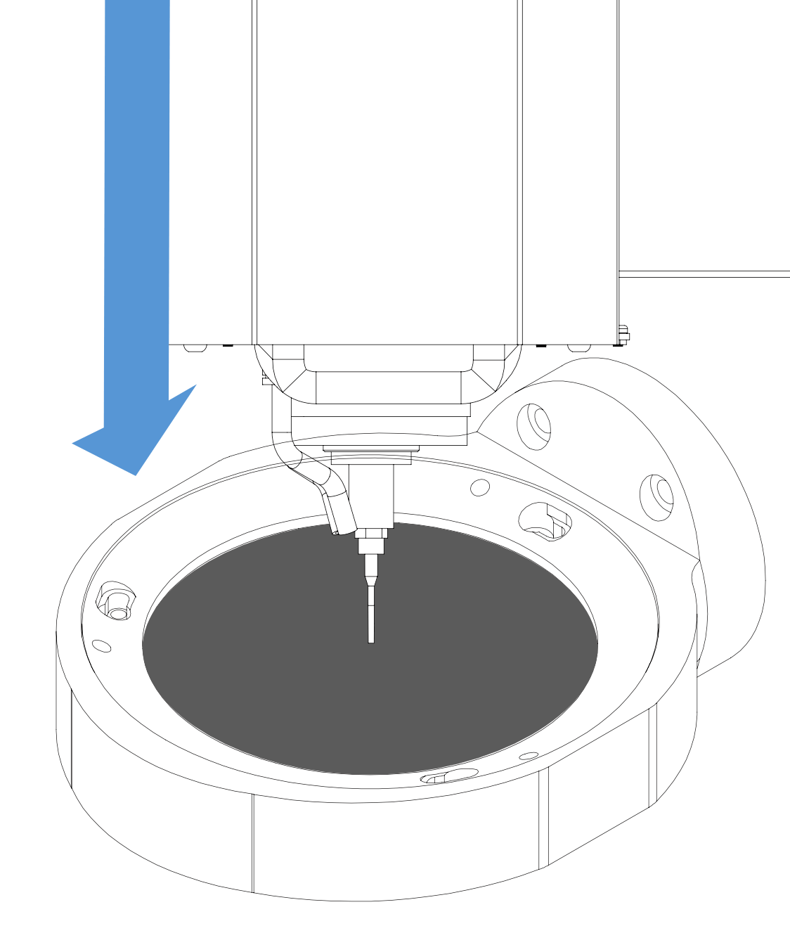
Move the Z-axis down, until couple of millimeters left to the wax.
Press "CW" to start the spindle.
Select 0.1mm on the jog control section. Lower the Z axis until it touches. Stop as soon as the tool toouches to the wax.
Stop the movement until there is a debris of wax when the tool touches.
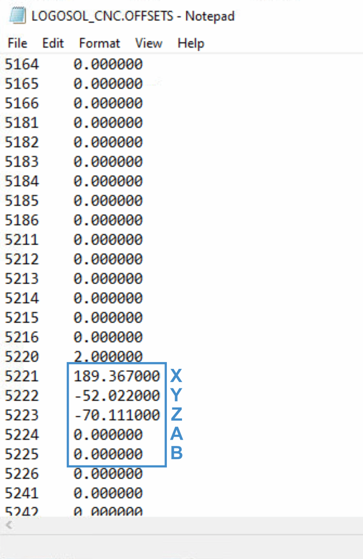
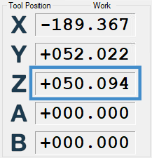
Click on the Z-axis in the tool position section.
Write half of your wax thickness in millimeters to find the center point. Then click "OK"
Warm up the machine then do the standard calibration. You can find the calibration guide on your machine's guide page.
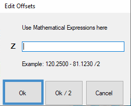
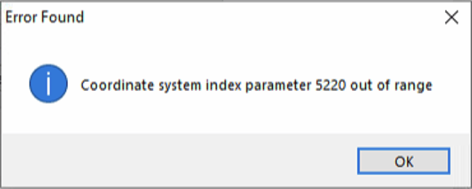
Required parameters out of range
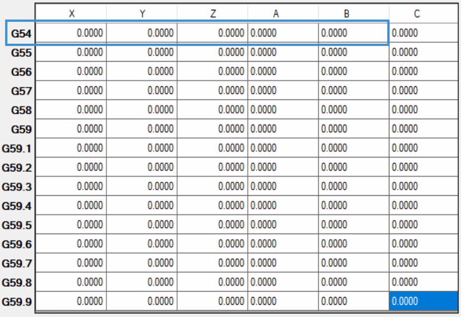
Click "OK" and check the active part offset.
Select G54 as the active part offset from the dropdown menu.
Communication error
Check if your USB cable that is connected to your tablet pc is loose or disconnected.
Rarely USB ports might malfunctioning therefore you can check by changing the USB port as well.
Chiller alarm goes off.
The chiller alarm could indicate that there is no circulation in your chiller. If this is the case then you should check:
Check if chiller hoses are folded or bent in any way that could prevent circulation.
Blow air into the "Chiller in" with an air gun or air hose to see if the air is coming out from the "Chiller out"
Software B limit violation
Check your CAM software B angles:
Navigate to this folder in your CNC computer.
This PC > Documents > YenaDent CAM 6 > TOOLPATH > Records
Open your calculated job here. Then navigate to the preparation tab. Then check your B angles on the disc.
Software Z limit violation
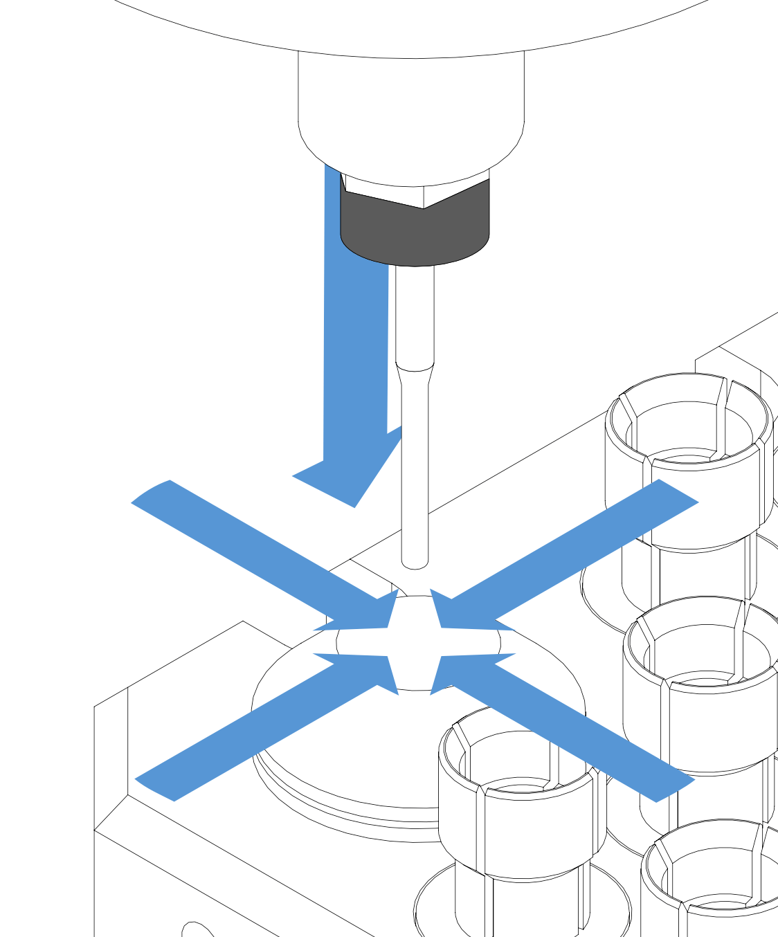
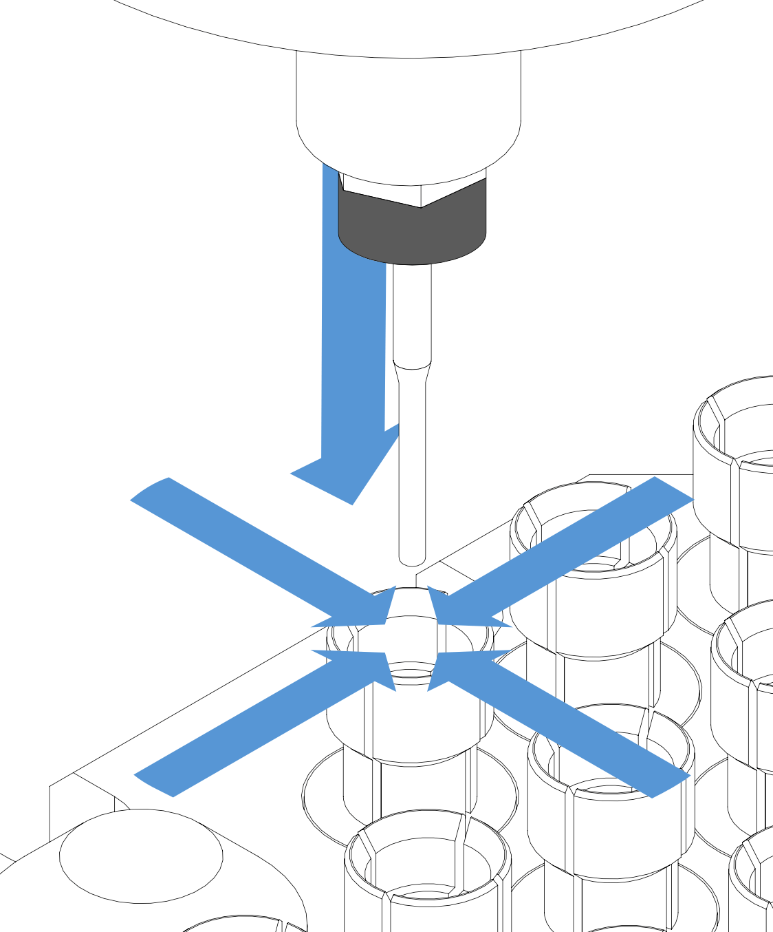
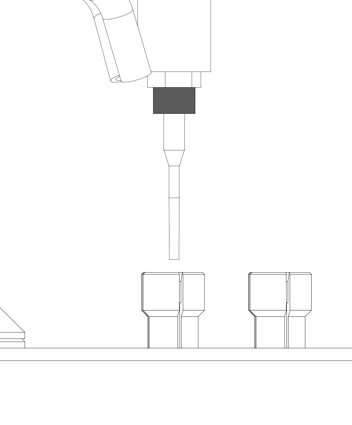
Measure all the tools the program is using with the "replace tool" button.
Error during tool measurement
Check the air.
Blue means there isn’t enough air pressure for machine operations.
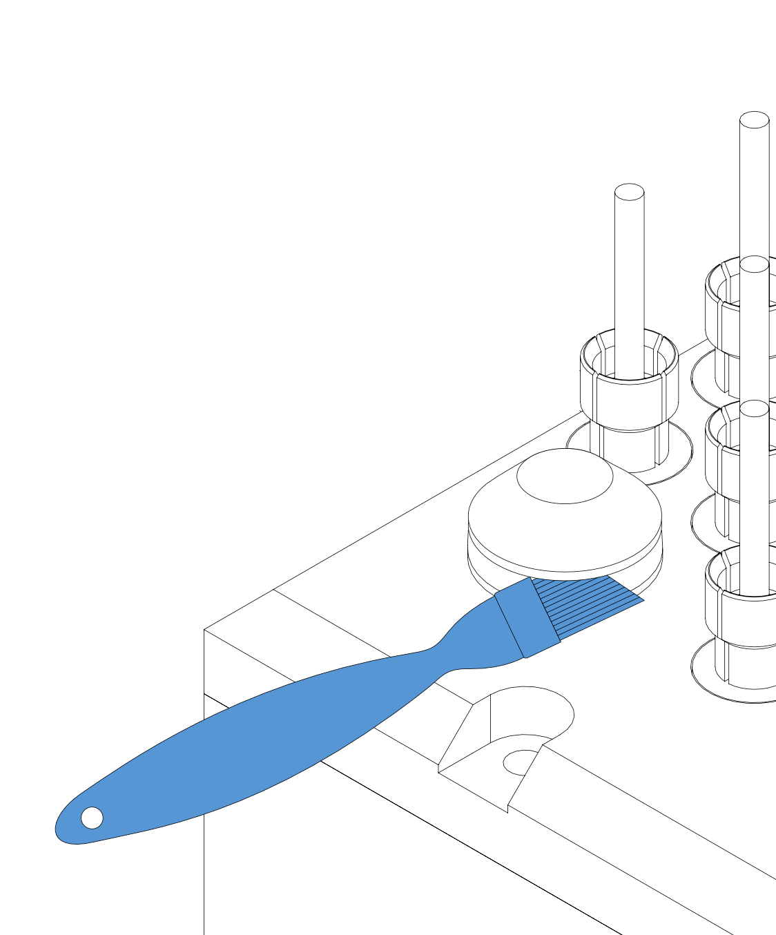
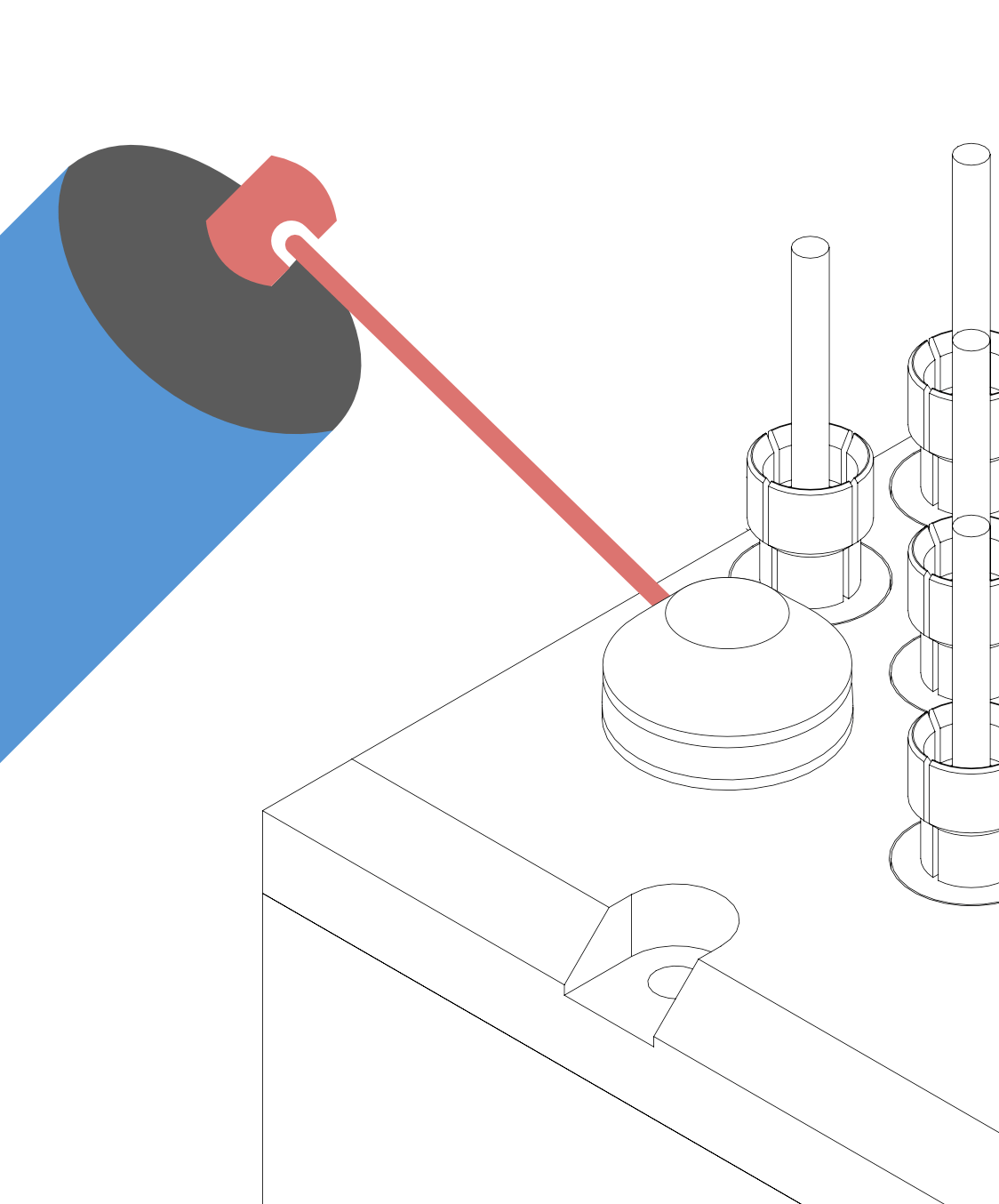
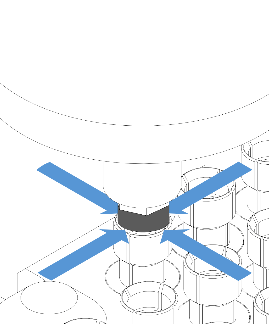
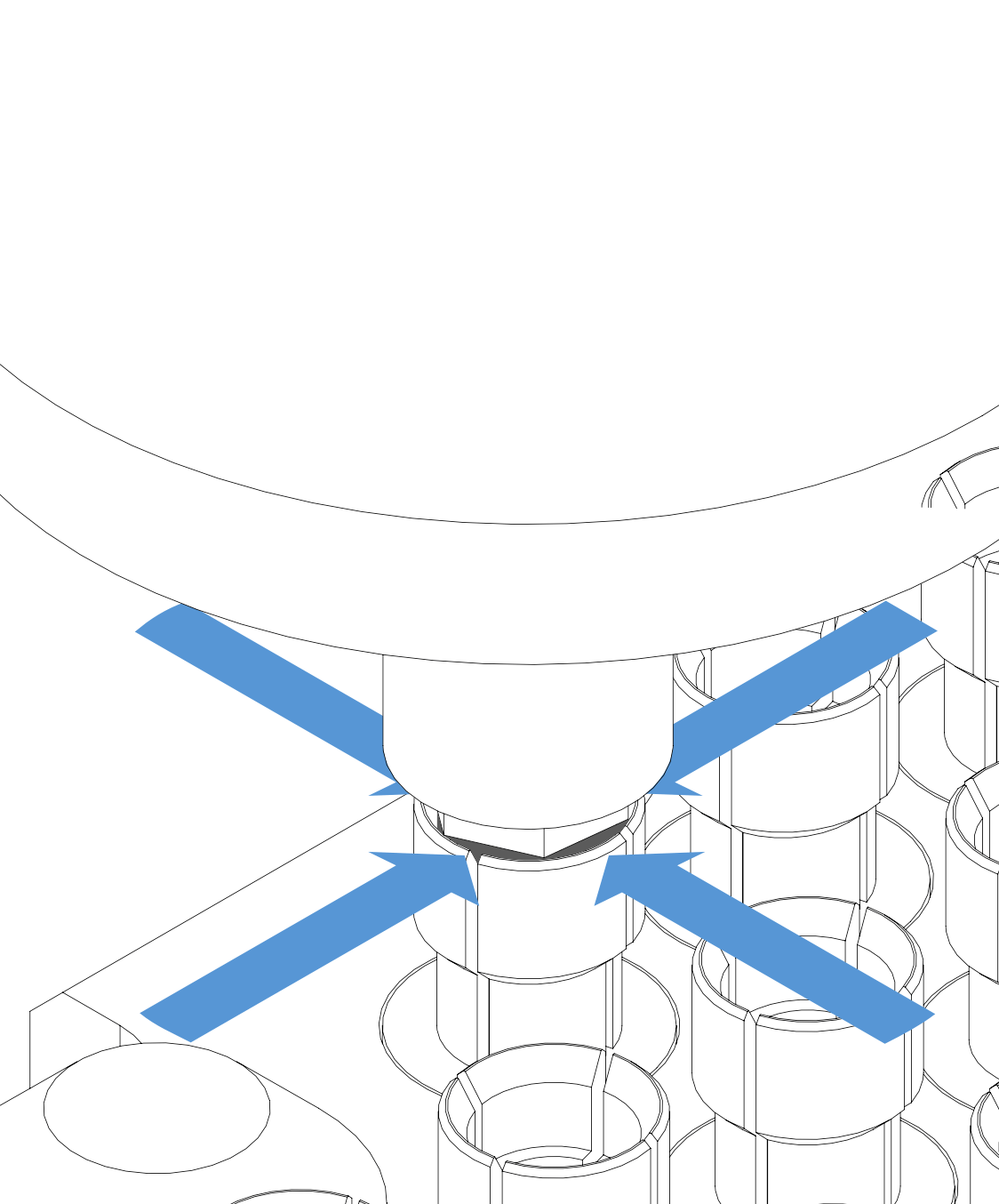
Check if your tool measurement sensor probe is getting stuck.
The probe can be checked by manually pushing it. Clean the probe if it is stuck.
You can clean underneath of the probe with a brush. After cleaning check with if the probe is free to move.
Brush might not be enough with wet milling. Zirconia and cutting liquid can be hardened. If that is the case please use a penetrant/lubricant sprey such as Wd40.
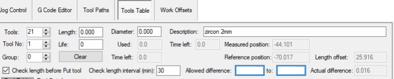
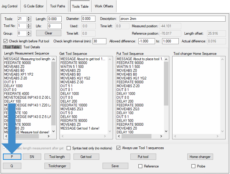
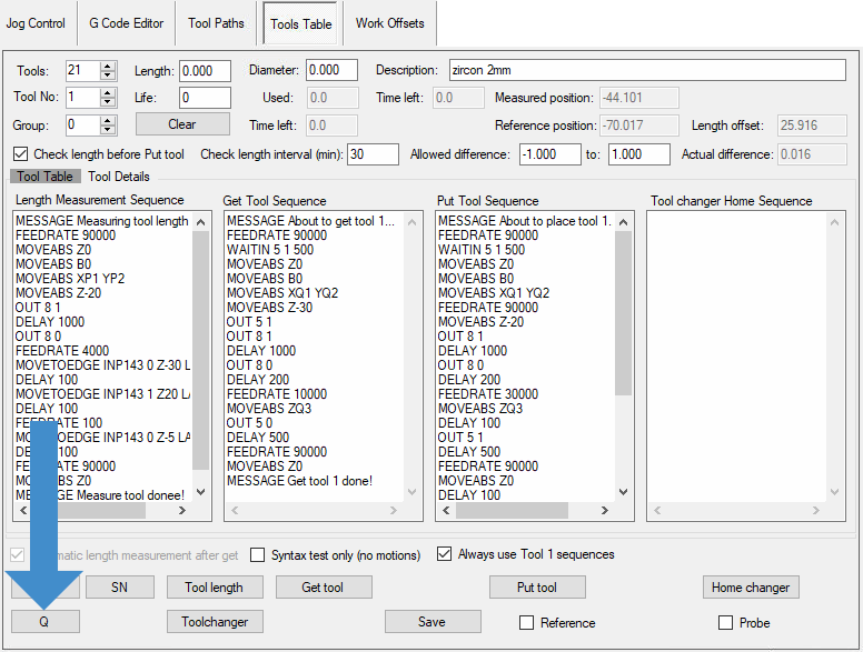
Check if allowed difference values deleted.
Service code is needed to access the jog control and tools table menu.
The password is: 9362
Enter "-1" to "1" inside the allowed difference boxes if they are deleted.
Click the "save" button after the adjustment.
Tool replacement table content show all "0"
Check if the contents of the ToolGroups file is deleted.
Turn the CNC program off.
Navigate to this folder in your CNC computer.
This PC > Local Disc (C:) > MCTL > PARMS
Open the "ToolGroups.setup" file.
If the contents are empty, download, copy and replace the ToolGroup file.
Measure all the tools on the pickup station using with the "replace tool" button.
Tool measurement error on line #X
Check the air.
Blue means there isn’t enough air pressure for machine operations.
Check if your tool measurement sensor probe is getting stuck.
The probe can be checked by manually pushing it. Clean the probe if it is stuck.
You can clean underneath of the probe with a brush. After cleaning check with if the probe is free to move.
Brush might not be enough with wet milling. Zirconia and cutting liquid can be hardened. If that is the case please use a penetrant/lubricant sprey such as Wd40.
Put tool error
Check the air.
Blue means there isn’t enough air pressure for machine operations.
Check if the contents of the ToolGroups file is deleted.
Turn the CNC program off.
Navigate to this folder in your CNC computer.
This PC > Local Disc (C:) > MCTL > PARMS
Open the "ToolGroups.setup" file.
If the contents are empty, download, copy and replace the ToolGroup file.